Péter Papp
Welcome to my personal page

High Power Switching Audio Power Amplifier with
symmetrical topology and digital control
A new symmetrical topology switching power amplifier is introduced for professional audio use. The amplifier is composed by a pair of semi soft switched half-bridges with independent feedback control. Whole overall layout looks very similar than an already bridge configured stereo amplifier with few exceptions. Although the complexity of the proposed topology is at least twice of the conventional single-ended Class-D amplifier it exhibits several advantages. The amplifier has full digital control of its every operational parameters.
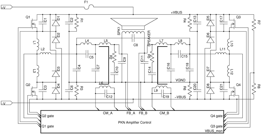
fig1.
Switching power amplifiers are only the way above few KiloWatts output power due their relative high energy conversion efficiency (typically above ~90%) with reduced cooling requirements. They could have much compact construction which is an unquestionable advantage over analog amplifiers* in case of space and weight sensitive applications. However a switching amplifier (typically Class-D) even with proper build quality and design usually is not as good in sound quality like an ultimate analog amplifier. We have developed a new symmetrical topology based on a pair of half-bridge configured inverter legs.It works with twice number of power devices on a single supply but one device is rated only for half of bus Voltage. It is an important feature that lower voltage switching devices could be used which have better switching characteristics than higher voltage MOSFETs. This effect gives less heat dissipations and nicer waveforms on the power devices.
Another advantage is that only one power supply is required and there is no serious current flow across the 'virtual ground' which effect is quiet common in the conventional single-ended topologies. Many of the Class-D amplifiers today has no real output feedback because of the problematic phase shift caused by the passive output low-pass filter. While these amps would have nice ratings on resistive load (filter is damped) everything goes wrong in real world operations since the speakers are never 'resistive-like' loads. Therefore we have established balanced Voltage feedbacks for each half-bridge inverter stages directly from the output points. With this method the voltage drop and gain errors vs. frequency created by the passive output filters are greatly reduced.
One Inverter leg is composed by a semi soft switched half-bridge configured MOSFETs and Ultrafast diodes. Some added inductors and capacitors are responsible for reducing the switching losses and lower the EMI noise floor. The half bridge is driven by just a minimal dead-time inserted between the counterpart conducting switching devices. This way the high frequency ringings during the commutation periods are lowered.
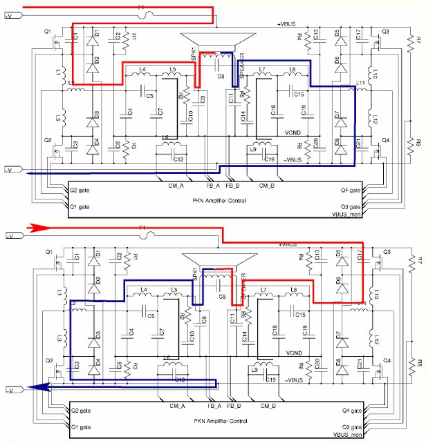
fig2.
The main current path responsible for creating output signal is shown on fig2. For compare them a conventional Class-D end stage is displayed on fig3. It is well understood that the symmetry of positive and negative current paths break in the conventional Class-D because of the separated power supply loops of positive and negative circuitry.
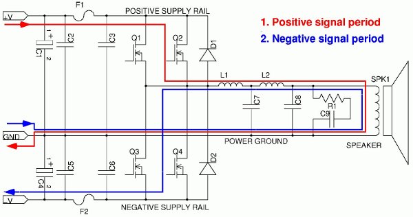
fig3.
Another problem is with the conventional Class-D that a large amount of current flows through its ground connections which could cause serious disturbances in the signal feedback. In case of higher power level (ex. above several thousands of Watts) it is very difficult to obtain good signal integrity/parameters with asymmetrical construction. The number of required switching devices take a relative large physical area on the board and the electrical connections with proper low inductance construction could be realized by only 4+ layers board. In contrast the proposed circuitry has better parameters even constructed on a 2 layer board.

fig4.
The complete output circuitry is displayed on fig4. from the component side. Number of output filter coils are twice than a conventional 'Class-D' amplifier which is costly but the splitted inductors have only half of the required inductance each and their total surface area is is much bigger than a single one. So these inductors carry relative high currents which heats up the windings and the cores too. In our case the total inductor power loss is distributed by two coils and the heat dissipation of losses happen on increased surface area. Coils are cooler and need smaller footprint on the board compared to the single-ended solution. The passive inductive filtering elements made from High temperature windings and metal- powder cores (Class-F grade). Main output filters are followed by several smaller filtering elements like HF resonant traps and 'Zobel networks' as artificial loading elements of the output stages.
All of the capacitors employed in the filtering circuits are the highest quality and have lowest ESR/ESL parameters on the operational frequency range. Remained high frequency ripple (>50KHz) on the load is pretty low compared to most of the 'conventional Class-D' amplifiers.
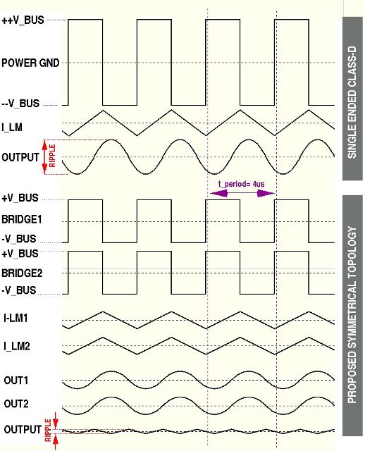
fig5.
On the fig5. The output ripple benefits of symmetrical topology is represented against conventional single-ended CLASS-D. Both circuitry run on 250KHz switching frequency equipped with similar overall characteristics output filters and the single-ended version has exactly twice of the bus Voltage than the Symmetrical. It means that the power output of compared topologies are pretty same. The speaker is connected between OUT1 and OUT2 in the symmetrical solution therefore the common-mode high-frequency ripple is neglected. So the single-ended circuit has much higher high-frequency ripple remained from the 250KHz switching signal than the proposed topology. Although the switching frequency is more than ten times higher of the audio bandwidth but the output conditions are much closer to a good analogue amplifier at least.
The whole amplifier module is controlled by a RISC microprocessor in real-time. All of the important operational parameters like input/output signal levels, currents, temperatures, different types of limiters and protective functions are maintained by the Main System Controller unit. We have established a fast full duplex optically insulated interface to the power supply unit for keeping the actual power requirements of the end stages always in the optimal range. The system Fig5. controller have informations about the power line levels and output actual speaker impedances as well. Our proprietary control softwares included the embedded power supply controls keep the amplifiers in the optimal operation range and prevents damage from environmental impacts. On Fig6. the amplifier module is displayed from the soldering side. Several circuit areas responsible for functions are marked. Most of the components are Surface Mounted Devices (SMD) for increased reliability and their reduced space requirements. The introduced amplifier module is used as a core of PKN Controls Xe and XD series.
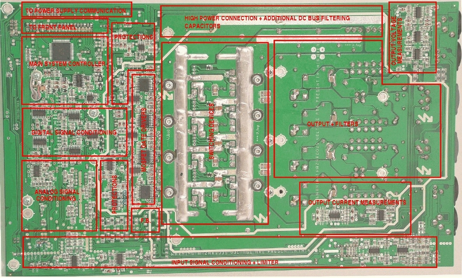
fig6.