Péter Papp
Welcome to my personal page

Ultra high power density
three or single phase operated high-frequency AC/DC converter
with active power factor correction for capacitor charging
applications
This paper presents a novel very flexible power supply for capacitor charging applications for example powering of the highest power professional amplifiers. The proposed converter has very wide input AC line range and operational on three or single phase with high power factor and low current distortion. Advanced high frequency power conversion lets the energy transfer and storage passive devices keep small and losses of active devices reduced by Zero Voltage and Zero Current (ZVS/ZCS) switching. With integrated magnetics and passives construction the power density of this converter exceeds 7500W/l and the power conversion efficiency is better than 94%.
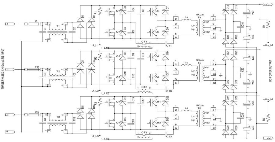
fig1.
Even with the fastest state-of-the-art power semiconductor devices the losses would be pretty high due to the operational frequency of the converter. Only in case of full soft ZV/ZC switching across the whole operational range it can match to the target conversion efficiency otherwise bulky heatsink would be required affects the power density. Another advantage of the soft switching is that the dV/dt stresses of the components greatly reduced which lowers the electro-magnetic interference issues. DSP has information about the input Voltages, input Currents, resonant tank parameters and charging rates as well as actual load balance of the charging cells. Implemented complex nonlinear digital control changes the operational frequency, pulse width with dead-times and phase shift of each individual cells maintains the best conversion point of the converter. Three individual cells have interleaved high-frequency operation by proper timings of switch drive pulses which fact becomes important when all cells connected in parallel mode (single phase operation).
A very unique feature of the proposed converter is that the AC Powering method could be selected easily by changing only the AC line cable (fig2.). Actual configuration of individual cells determined by the power plug arrangement. The input power socket is fixed while two types of power cables can be used for AC connection, one type with four wires (L1, L2, L3, PE) for the three phase operation and another type with three wires (L, N, PE) for the single phase operation. Probably it is the easiest and most failure-proof way of 3/1 phase operational selection by the end user without the risk of misconfiguration risks (fig3.).
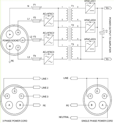
fig2.
could mean much less copper cross-section area requirement and a better cost-effective power distribution. Three phase operation with high power factor and low line current shape distortion has the advantage of best interfacing to power sources, AC distribution lines or diesel generators. The converter is able to handle the worst voltage balance problems across the line conductors and even remains operational with two phases*.

fig3.
parameters of high frequency converters for the best charging characteristic. Although the advantages of true three phase
powering has lost (high voltage, relative low current skinny line cable and small low-frequency ripple) however the parallel
configured converters can pull out three times of the current from the single phase line. Thanks to the hardware and operational
mode changes the overall conversion efficiency of power supply is not much worst than in three phase case. When all of the
converters connected in parallel it would create huge current ripple on the line what is difficult to handle (even at so high frequency
many bulky line filtering elements would be required). The proposed solution has a special phase-shifted synchronization
between the individual converters which dramatically reduces the current ripple by the number of units connected. Not only the size and cost of EMI input filter reduced by interleaving and proper phase-shift control but the output high frequency ripple too. It
means lower high-frequency current stresses across the output energy storage elements. Overvoltage events (like accidental 400V
fig3. connection in single phase mode) are not problematic unlike most of the single line power supplies on the market now.
The three phase operation is far better than single in the light of low-frequency output ripple conditions of the converter. This fact is even more important when the converter act as a power supply of low-frequency amplifier. However in certain applications issues of this elevated ripple can be compensated by the proper sizing and number of the output energy storage capacitors.
Very high operational frequency is required to keep the passive energy transfer elements small, especially the size of power transformers and inductors depend on the frequency of magnetizing current. Above ~250KHz the Skin-effect becomes significant part of contributing the overall power losses of conductors so the layout is critical. Most of the conventional wire-connected devices would not work very well so We have integrated most power semiconductors and passive devices in the same structure. This way the length of high-frequency interconnections could be reduced and it greatly helps to improve the power density. When lots of heat sources (power coils, semiconductors) placed in pretty close proximity each other most of the conventional air-convection based cooling concepts would not be so effective since there is just limited surface area or even no room for the airflow.

Waste heat removed from the heatsink via forced air cooling by regulated speed DC fans. Actual speed of fans depends on the momentary load and charging conditions. The whole 15KJ/s peak charging capability power supply includes heatsink, connectors, input filter and fuses consumes just less than 2Liters in volume so the actual power density of converter is more than 7500W/l. A prototype of the proposed converter is shown bellow. It includes a 50W universal-line auxiliary housekeeping power supply too. The dispayed view is from the heatsink side and does not contain the heat transfering elements. One of the proposed converter powers a PKN 3PHASE-20K while two of them is the heart of the PKN 3PHASE-40K professional amplifiers.